Well, here's a good start:
https://www.pistonheads.com/gassing/topic.asp?h=0&f=66&t=1451342
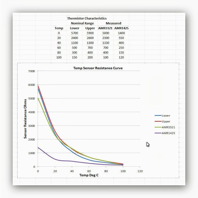
Look at the graph of the gauge's temperature sender's resistance - essentially, at 100C (212F) AMR1425 (used on 14CUX and GEMS vehicles) has almost the same resistance as AMR3321 (used on 300TDi), but the latter has much steeper temperature dependence across the entire temperature range.
It has the same physical dimensions, so if one fitted a 300TDi sensor to a GEMS truck instead of a factory sender, my guess would be that the temperature gauge needle would move much faster beyond half scale.
If you are diligent, here's the course of action you can take (knowing that no two sensors or two gauges are alike):
(0) Buy, borrow, or steal a variable resistor (500 Ohm should do fine), and connect a fixed 50 Ohm resistor in series with it, and attach a pair of alligator-clip wires to the the resistors (variable in series with fixed); you will also need an ohmmeter.
(1) Disconnect the wire going to the gauge temperature sensor - see the picture for which one it is:
(2) Adjust the variable resistor to the maximum resistance.
(3) Connect the alligator clips - one wire to the engine block, another - to the wire that was connected to the temperature sender.
(4) Turn on the ignition but don't start the engine.
(5) slowly adjust the variable resistor until you see the temp gauge needle to hit the bottom of (what you like to be) the temperature scale.
(6) Turn OFF the ignition, disconnect alligator clips, and measure the resistance. Write it down someplace.
(7) Replace the alligator clip wires, turn on the ignition, and slowly adjust the variable resistor until you see the temp gauge needle to hit the top of (what you like to be) the temperature scale.
(8) Turn OFF the ignition, disconnect alligator clips, and measure the resistance. Write it down someplace.
The rest depends on your findings. I have not done this, so take it with a grain of salt - or do your Google fingerwork because somebody already did this and has the decent answers.
(9) Low temperature limit: we know that the gauge barely hits the second hash from the bottom (low limit of normal range) around 160F. The factory AMR1425 sensor should have a resistance of ~200 Ohms, give or take.
(10) High temperature limit: we know that the gauge doesn't do diddly between 160F and approximately 225F, after which it quickly migrates to "You're fucked" zone. The factory AMR1425 should have a resistance of ~100 Ohms at this temperature, give or take.
So, I assume your desire is to make this more linear in the range between 160F and 230F. This can be accomplished using two resistors - one in series with the temperature sender, and one - in parallel.
If you use AMR3321, its resistance close to 160F and 230F will be about 520 Ohm and 50 Ohm, respectively.
So, adding a 50 Ohm resistor in series with AMR3321 will bring the 230F point on the temperature gauge where you want it.
The total value of AMR3321 and 50 Ohm resistor in series at 160F will be 570 Ohm, and your aim is to reduce it to 200. You can do it by connecting one more resistor in parallel to the whole thing; its value can be calculated as
R = 1/ ( 1/200 - 1/570) = 308 Ohm (300 is the closest common value).
Note also that adding a 300 Ohm resistor in parallel to sender+50 Ohm circuit will also decrease the top temperature setting - although not by much.
Here's the circuit diagram:

(11) Drain some coolant, replace AMR1425 with AMR3321, add back coolant, wire up both resistors and shrink-wrap everything that might create an electrical short.
(12) Start the engine, and verify the action using an IR gun. I am curious to see if that actually works - but why should it not?
Lowering the value of R1 decreases the temperature corresponding to the desired HIGH position of the needle on the scale.
Lowering the value of R2 decreases the temperature corresponding to the desired LOW position of the needle on the scale.
Note that the total resistance will never get below 300 Ohms, so effectively the needle will jump to that LOW mark as soon as you turn ON the ignition
and will move off that mark only beyond that set temperature. So I'd aim for the very lowest recognizable needle position, and calculate what is needed to get it to correspond to ~40-50C. You have to use your measured resistance values to calculate what's needed to make it so.
P.S. If I ever get around to do it, I'd aim for the end "normal' range to be from 100C (212F) with a 70C thermostat, to 105-108C with a 80 to 95C thermostat.