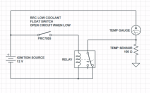
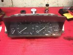
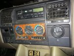
We all know the temperature gauge is useless. Adding an auxiliary temp gauge or a scan gauge clutters up the interior, and reworking the factory gauge to more linear would likely cause a panic attack when the needle isn't exactly where its been for the last 25 years.
I'm about to fire up a new engine so making certain it doesn't overheat is top of mind. I started to design a circuit to tap into the temp sending unit and compare it to a preset voltage and make a light on the dash blink when it hits a certain sending unit resistance. When I got around to assembling the circuit on a spare gauge cluster I discovered Land Rover had already designed a similar circuit but for whatever reason decided to not populate the circuit board.
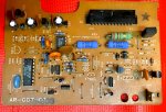
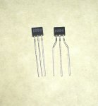
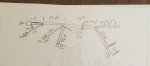
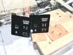
Its a mix of diodes, resistors, and transistors. I salvaged most of it from another spare board, but I'll put together a BOM once I test it on a real vehicle.
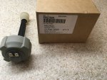
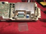
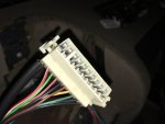
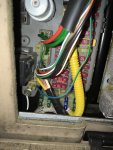
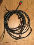
They left off a couple of traces on the flexible circuit board on the gauge cluster, you need to run wire from the ground side of the light and from the temp sending unit. I tried soldering and I'm really glad this is a spare gauge. I'll be using some conductive epoxy on the next one. And for wire strain use silicone. I first used some MEK based adhesive and it started to dissolve the flexible circuit board.
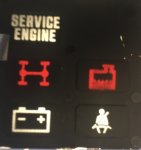
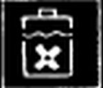
Below is a video of its operation. I've exaggerated the needle movement by shorting it. I have it set to go on around 29 ohms which is about 230F. At that temp the needle is still parked in its normal slightly below middle position.
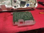
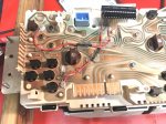
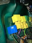
The images are the flexible circuit board jumper wires, the unpopulated gauge driver board, and the populated board. There are a few items I left out of the board, and the brown wires are for testing. They would be a solid jumper in normal operation.


I'm about to fire up a new engine so making certain it doesn't overheat is top of mind. I started to design a circuit to tap into the temp sending unit and compare it to a preset voltage and make a light on the dash blink when it hits a certain sending unit resistance. When I got around to assembling the circuit on a spare gauge cluster I discovered Land Rover had already designed a similar circuit but for whatever reason decided to not populate the circuit board.
Its a mix of diodes, resistors, and transistors. I salvaged most of it from another spare board, but I'll put together a BOM once I test it on a real vehicle.
They left off a couple of traces on the flexible circuit board on the gauge cluster, you need to run wire from the ground side of the light and from the temp sending unit. I tried soldering and I'm really glad this is a spare gauge. I'll be using some conductive epoxy on the next one. And for wire strain use silicone. I first used some MEK based adhesive and it started to dissolve the flexible circuit board.
Below is a video of its operation. I've exaggerated the needle movement by shorting it. I have it set to go on around 29 ohms which is about 230F. At that temp the needle is still parked in its normal slightly below middle position.
The images are the flexible circuit board jumper wires, the unpopulated gauge driver board, and the populated board. There are a few items I left out of the board, and the brown wires are for testing. They would be a solid jumper in normal operation.