| Author |
Message |
    
R. B. Bailey (Rover50987)
| | Posted on Monday, January 13, 2003 - 11:32 am: | 


|
The switch that is available for aux. lights looks like it goes into the empty slot next to the C.C. master switch - is that right? Or do I need to buy a whole new switch bay to accomodate the extra?
If it will work in the existing bay; is there a circut already feeding that slot, just not hooked up, or do I need to do a fresh wire all the way through?
How do I get the stupid blank switch out so I can put the new one in?
I have the wiring diagram, so I am looking for some more practical info on how to actually make the thing look good in the cab, that is why I want to buy the LR switch and put it where it belongs.
Thanks for your help - and the great PHOTOS that I know you all have to show me just how it would be done!
http://landrover.mrbaileyshistory.net |
Glenn Guinto (Glenn)
| | Posted on Monday, January 13, 2003 - 11:38 am: |
|
Follow this link and click on the Hella 4K's album
-glenn |
Paul D. Morgan (V22guy)
| | Posted on Monday, January 13, 2003 - 12:10 pm: |
|
Mr. Bailey,
"How do I get the stupid blank switch out so I can put the new one in?"
Pull on it and it will release from the binnacle.
"I have the wiring diagram, so I am looking for some more practical info on how to actually make the thing look good in the cab, that is why I want to buy the LR switch and put it where it belongs."
Your decision will rest on what wiring path you chose. I.E; Are you going to tap into the BCU or are you going to stay external of the vehicle electronics?
BCU = momentary switch (Fog light switch)
External = on/off contact switch (rear wiper switch)
Check out:
http://www.discoweb.org/lights
LR binnacle switch covers can be swapped out and yes you can add or move switches inside the binnacle. A bit of alteration using a knife might be required.
Hope this helps,
Paul
'00 Rover |
R. B. Bailey (Rover50987)
| | Posted on Monday, January 13, 2003 - 12:27 pm: |
|
Glenn - thanks for the pics, why are there two blue wires in some, and only one in others? Very informative - I'm a visual learner... |
Glenn Guinto (Glenn)
| | Posted on Monday, January 13, 2003 - 12:40 pm: |
|
Mr Bailey, the two blue lights go to the two lights that I have. They share one connection to the relay. I am not an electrician by any means but I did this on my own based from what I learned from this site. It even has the pin outs for the factory fog lamp switch. Good luck on the project!
-glenn |
R. B. Bailey (Rover50987)
| | Posted on Monday, January 13, 2003 - 12:50 pm: |
|
Just from looking at your pictures it looks like you did a direct wire job from the battery to the relay to the switch to the lamps - or close to that order. Looks simple, the way I would do it, makes sense, I will order the switch this week! |
Greg P. (Gparrish)
| | Posted on Monday, January 13, 2003 - 12:53 pm: |
|
Paul, Looks like Mr. Bailey has a D1, so his wiring is going to be different than yours and mine. |
Paul D. Morgan (V22guy)
| | Posted on Monday, January 13, 2003 - 06:27 pm: |
|
Same concept though. |
John Moore (Jmoore)
| | Posted on Monday, January 13, 2003 - 08:36 pm: |
|
Hey, guys I have a 99D2 and I am about to wire hella 4000's on the brush bar. On the D2 where did you go through the firewall? Also, where are you mounting the fuse, relay and terminal blocks. I like the idea of having room to grow.
I am using the hella wiring harness.
TIA
-John |
Paul D. Morgan (V22guy)
| | Posted on Monday, January 13, 2003 - 08:57 pm: |
|
Hey John,
On your D2; there is a hole on the DS firewall that is filled with a rubber grommet. This is where I entered the cockpit.
I used Hella Wiring Harness's as well and mounted the relays on the back firewall on the passenger side. But since you are mounting the lights on the fire wall, I would mount your Hella Relay on the structure that is outboard of the battery box. You have to remove the battery to see what I mean. This location has a lot of room, in fact this is where my IPF relay is for my bumper lights.
Email me at work tomorrow if you have any more questions. [email protected]
Paul
'00 ROVER |
John Moore (Jmoore)
| | Posted on Monday, January 13, 2003 - 09:12 pm: |
|
Thanks Paul,
I just went and looked at the battery box. I see what you mean. Plenty of room, that would make for a clean install.
I could not find the rubber gromet on the DS firewall. Is it located near the master cyclinder? (SP)
-John |
Paul D. Morgan (V22guy)
| | Posted on Tuesday, January 14, 2003 - 06:18 am: |
|
John,
Go into your cockpit on the DS and look at the forward bulkhead at the location where the carpet ends. It should be up in the forward rh corner of the DS underside. Or.....Go into the engine bay, behind the brake resevoir, follow the fender bulkhead / firewall corner down and you should see it. Look for a point in the firewall that the wiring from the engine bay enters the cockpit. I.E., follow the black flexible conduit.
Paul |
John Moore (Jmoore)
| | Posted on Tuesday, January 14, 2003 - 07:32 am: |
|
Thanks! I'll have a look this afternoon.
-John |
Greg P. (Gparrish)
| | Posted on Tuesday, January 14, 2003 - 10:05 am: |
|
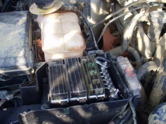
Another alternative:
 |
Greg P. (Gparrish)
| | Posted on Tuesday, January 14, 2003 - 10:07 am: |
|
I actually mounted mine on a board cut to shape to drop into my jack holder. I got the parts from www.rallylights.com and everything wires to this point. I have extra spots for future projects if I need them. |
R. B. Bailey (Rover50987)
| | Posted on Wednesday, January 15, 2003 - 12:53 pm: |
|
Thanks for all the info. Now, one more question: Where do I ground the light? It is on the rear corner of the roof rack with two wires coming from it that are equal length (about 3 feet.) Should I ground at the mount point, on the body somewhere, or just at the switch/relay, as is shown in Glenn's photos? |
Jack (Olered)
| | Posted on Wednesday, January 15, 2003 - 01:14 pm: |
|
I have a question. I've connected my H4000s using the Hella harness with a LR fog light switch (the one that fits beside the CC switch-99D1). I've tried what seems like a bazillion different combinations to get the light on the switch to engage with depressed. The light is on constantly. When my headlights are turned on the light goes out and vice-versa. Can anyone shed some light on this? I've ordered 4 more lights and would like to correct this problem next time.
Thanks |
Greg P. (Gparrish)
| | Posted on Wednesday, January 15, 2003 - 01:48 pm: |
|
Mr. Bailey,
I grounded all of mine back at the battery area. I have a terminal block for positive feeds visible in the picture above, and a terminal block for negative feeds (not visible). I ran a separate 12 gauge power and 12 gauge ground for each of my 5 lights. It is a lot of wire to get up the outside A pillar, but thats what I did. If I did it again, i would probably run a ground strap up to the roof rack, and run a smaller 14 gauge wire to each power wire. Then just ground each light with a terminal loop around the mounting stud. One thing I can probably not have to worry about with my setup will be rust on the grounding points, but that may not be a problem if you can find some stainless terminal rings. |
R. B. Bailey (Rover50987)
| | Posted on Wednesday, January 15, 2003 - 09:53 pm: |
|
OK, my simple mind is starting to grasp this simple wire job once and for all. But I do have a few more questions I need answered. First, to help myself I diagramed the job as I am seeing it happen right now. Please follow this link to my kindergarten drawing of a Hella wire job and tell me if it would work:
http://landrover.mrbaileyshistory.net/graphics/hellawire.pdf
Don't pay any attention to my "official" looking symbols on the diagram, they are completely made up!
Second, just to make sure, the ground from the light and the relay do NOT have to go all the way back to the battery, as long as they are "properly" grounded right? Or what?
Third, the 12v power source going to the switch... where do I get that? (Is this what you were talking about above Paul? BCU or External?) OR, CAN I JUST GET THAT POWER FROM THE BATTERY? I assume (remember my feeble mind is at work here) that if I get that from the battery I can then use the light with or without the key being in the ignition? Or will that simply melt my switch or some other bad thing? Basically, where do I patch into that 12v?
Again, thanks for all your help, this web site is great! (I have asked Doug Shippman about this, but if any of you know him, his answers about complicated things are almost more comical than helpful unless you really know what he is talking about. In this case I just nodded and said, "yes." Of course, that does not mean he doesn't know what he is talking about.) |
Glenn Guinto (Glenn)
| | Posted on Wednesday, January 15, 2003 - 10:19 pm: |
|
Bailey, that's pretty good. I too was apprehensive at first but once you get started everything will start to make sense. But you pretty much got the idea there. Except if you're using the hella wiring harness, the fuse is attached to the relay already. Just plug and play! 
The 12V wire in question can be tapped into your headlamps so you can only turn your H4Ks when you have your headlamps on. I think (not sure and it's too damn cold to check outside) I tapped mine to the cruise control fuse so I can only turn them on if the car is running (avoid draining the battery this way). Good luck!
-glenn |
Greg P. (Gparrish)
| | Posted on Wednesday, January 15, 2003 - 10:24 pm: |
|
Glenn is right about the 12v lead you are asking about. I tapped into my running lights, that way I can run mine independent of the head lights, but there is a beeping reminder from the running/headlight switch if I get out of the truck with lights on. I didn't want to have to have my head lights on just to turn on the rear work light. Make sense? You could go straight to the battery, but you do run the risk of leaving a light on and draining the battery. |
R. B. Bailey (Rover50987)
| | Posted on Thursday, January 16, 2003 - 01:13 am: |
|
I am not using a harness, I'm doing it from scratch using the LR switch and Hella relay, I now need to get a good fuse block or single plug-in-thingy. I am thinking I will go straight to the battery though so that I can just hit the switch without having to get my lazy butt into the car, and put my lazy key into the ignition, or go through all the trouble of actually turning on the headlights, then the work light. Anyway, I doubt I would forget that the work light is on. I will be putting my fog lights into the headlight power though.
Sooo... exactly where do I tap in? Say for the running lights; at the switch? At the fuse? |
R. B. Bailey (Rover50987)
| | Posted on Thursday, January 16, 2003 - 01:14 am: |
|
Actually, let me say again: pictures of where and how it is tapped in would be great! Don't you love digital cameras? |
R. B. Bailey (Rover50987)
| | Posted on Thursday, January 16, 2003 - 01:18 am: |
|
I guess what I am asking is when you say "tapped in" do you mean I actually do a splice of a 12v wire, say in the running light on a headlight? |
Glenn Guinto (Glenn)
| | Posted on Thursday, January 16, 2003 - 07:47 am: |
|
Well, they have 'adaptor' thingies that you can buy where it's attached to the wire, then plugged in to the fuse box. The fuse then plugs in to the 'adapter'. Kinda like the christmas light plug, you can still plug something behind it. I tapped into the fuse box on mine. Hope this helps. Greg or Paul might have a better idea. Good luck!
-glenn |
Paul D. Morgan (V22guy)
| | Posted on Thursday, January 16, 2003 - 07:55 am: |
|
Mr. Bailey,
I used a clamp splice to tap into whatever wire I needed for switch power. They are available at any autoparts store. Just simply place the power source wire on one side and your wire on the other side, close and clamp down with pliers.
Paul
'00 ROVER |
Greg P. (Gparrish)
| | Posted on Thursday, January 16, 2003 - 08:45 am: |
|
You know, it sounds easy enough to say you would not forget it was on, but if it is daylight, you can't always easily notice that a light is still on when you get out of the car.
On another example, and I'm gonna tell on Paul for this one, we drove up to Easton, PA, from Philly area to help Randy Maynard install some sliders and springs/shocks one Saturday or Sunday. Paul was following me on the way up, and when we got to within 1 or 2 miles of Randy's we miss our turn. In the process of turning around, Paul winds up in front of me and I notice his work light is on and has been on the whole drive up (1.5 hours). Now, this may not be a big deal when you are driving up, but that could be a big deal if he got out of the car on Saturday morning and left it on all day.
Just my 2 cents on the power source for the switch. |
Greg P. (Gparrish)
| | Posted on Thursday, January 16, 2003 - 08:48 am: |
|
On the tap in point, if you do use the running lights, simply route your wire down the drivers side of the engine compartment and you can access the running lights wiring behind the front drivers running light. It comes off with one phillips style screw at top and then you pull it out. It is held mostly with plastic pegs that pop in/out of holes.
Just find the 12v positive feed going to the running lights and use one of the "tap in" type wire clamps that Paul is talking about. You can get them most anywhere like Pepboys, walmart, NAPA, etc. |
Paul D. Morgan (V22guy)
| | Posted on Thursday, January 16, 2003 - 10:23 am: |
|
Yeah, what kind of Jackass would drive for 1.5 hours with a back up light on..... |
R. B. Bailey (Rover50987)
| | Posted on Thursday, January 16, 2003 - 10:36 am: |
|
I'm set, all I need is the actual switch and I'm in, thanks for all your help. I will take pictures and let you know how it goes. Thanks
http://landrover.mrbaileyshistory.net |
Glenn Guinto (Glenn)
| | Posted on Thursday, January 16, 2003 - 10:39 am: |
|
Bailey, call Nathan...discountrovers.com for the stock fog lamp switch. Good price! While you're at it, you might want to order two to fill those blanks and for future use. Also, I ordered the stock rear fog lamp switch that I plan to use for my rear work lamp. Just haven't found some time to work on it yet but I plan to ditch one of the radio volume controls (non-stock radio) in place for it. Good luck on your project and maybe you can document your install and send it to Ho for future reference!
-glenn |
Jack (Olered)
| | Posted on Thursday, January 16, 2003 - 11:02 am: |
|
Any input concerning my post above?
Thanks |
Glenn Guinto (Glenn)
| | Posted on Thursday, January 16, 2003 - 11:08 am: |
|
Sorry Jack, I have exactly the same issue. I also tried pretty much everything I know (which is not much...lol) just don't pay attention to it now.
-glenn |
R. B. Bailey (Rover50987)
| | Posted on Thursday, January 16, 2003 - 11:22 am: |
|
oh, that reminds me, the switch bay that I have is different than the one you have in your pictures Glenn. Mine has one solid blank on each side, one empty blank that I can pop out easily, and the space that is being used for my CC switch. Right now it looks like I only have room for one light switch!
I am going to document it and make it look easy for people like me.
htpp://landrover.mrbaileyshistory.net |
|