| Author | Message | ||
Bruce little (Blittle) New Member Username: Blittle Post Number: 1 Registered: 03-2003 |
I'd like to hookup the trailer wiring from my '97 Discovery to a (very) small boat trailer which uses a small standard 4-pin flat connector. I've read numerous discussions on this site, and others, but none seem to use the same connector, or seem to rely on colour for guidance (and I'm colour blind). I only use this trailer a few times a year and don't really feel like spending $200+ US dollars (~$1,000,000 CDN) for a LR factory adaptor. I'm curious as to whether I can purchase a standard 4-pin extension wire, cut off one end, and splice it to the wire feeding into the existing 7-pin round connector. I was considering using "blade type" connectors which would allow me to make the connection without in any way destroying the existing wiring. Or better yet, is there a simple adaptor that can be purchased somewhere. Some sites which provide some limited guidance,reference a tail light convertor. The sites I'm thinking of include; http://www.cs.odu.edu/~glaves/chris/trailer/hook.html#Tail%20Lights%20Converter and http://www.discoweb.org/uhaul/index.htm Am I wrong in thinking that for a standard flat 4-pin connector (simple brake/turn/tail lights, no power brakes or power supply etc.) that I should be able to complete the wiring using simple splicing? If not, what exactly does the tail light convertor "convert"? Any help that can be provided would be greatly appreciated. | ||
gp (Garrett) Senior Member Username: Garrett Post Number: 1861 Registered: 10-2001 |
the second link you have there from dweb is what you want. takes all of 5 mins., $20-25 and you are ready to trailer. | ||
Bruce little (Blittle) New Member Username: Blittle Post Number: 2 Registered: 03-2003 |
Thanks Garrett, But the colours referenced don't match the wiring I have, and there is not enough detail in the photograph for me to identify the correct sequence. If I hold the 4-pin connector (which plugs into the trailer wiring) in front of me I get the following from left to right. a male pin, fed by a white wire, a female socket, fed by a brown wire, a female socket, fed by a yellow wire, a female socket, fed by a green wire, Again, thanks to anyone for any help. | ||
gp (Garrett) Senior Member Username: Garrett Post Number: 1865 Registered: 10-2001 |
do your wires look like mine? i have a '96. if this still does not help get a multi meter and test your wires while brakes are on, turn signals, etc. that way you will know what is what. 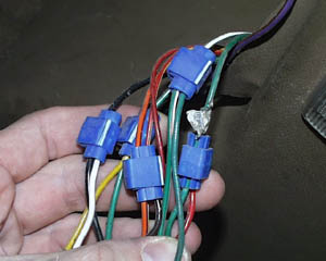 | ||
Bruce little (Blittle) New Member Username: Blittle Post Number: 3 Registered: 03-2003 |
Hi Again, I'm sure their similar (like I said I'm colour blind). Right off the bat I notice you've got 5 connectors in your photo, even though I'ver only got 4 wires. I'm guessing the difference comes from the US standard adaptor using 1 feed for the tail/brake light, and the UK connector using one for each. My understanding is that I can use one or the other. | ||
gp (Garrett) Senior Member Username: Garrett Post Number: 1866 Registered: 10-2001 |
ah. didn't catch that you were color blind. again your best bet to make sure it to test each wire then use the chart on this site to make your connections. good luck. | ||
Bruce little (Blittle) New Member Username: Blittle Post Number: 4 Registered: 03-2003 |
Garrett, I've put a photo of the connector on web page here; http://www3.ns.sympatico.ca/blittle/connector.JPG Has anyone spliced a connector like this into wire feeding 7 pin round connector? | ||
John Steczkowski (Stecz) New Member Username: Stecz Post Number: 4 Registered: 02-2003 |
I had an official LR trailer hookup on my '97 Disco, which worked fine, but proceded to go bad. Apparently they are difficult to get (maybe because they constantly go bad). So what I did was go to Pep Boys and get the brake light adapter box. I then cut off the plug going into the old box (not the truck wiring, just the adapter wiring). I tested each wire and it turned out that the colors exactly matched my new adapter box, so I just spliced it together and it's been working ever since... | ||
gp (Garrett) Senior Member Username: Garrett Post Number: 1868 Registered: 10-2001 |
bruce that is what i spliced into mine. least i think so. just your standard flat 4 connector. |