By Matt Moe
April 23, 2002
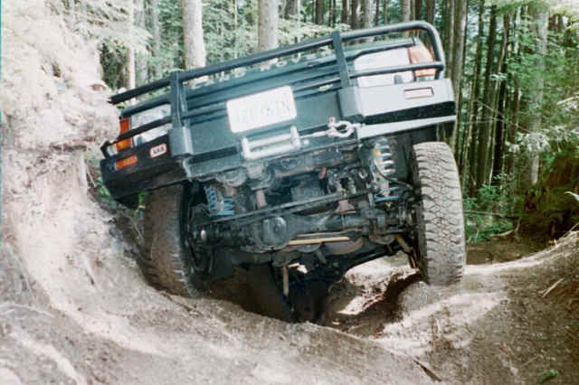
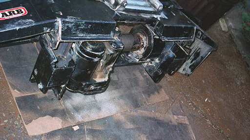
This article replaces an earlier version where I documented my installation of the Ramsey RE winch in the ARB (air bag) bumper. I was not satisfied with the first attempt for three reasons. First, the winch sat too low and was unprotected and vulnerable to damage. Second, the ARB air bag bumper had taken a few hits and shown that it was susceptible to twisting especially at the point where the crush cans bolt to the bar. Finally, I wanted to improve the approach angle. To address these issues, I decided to relocate the winch higher and trim the ARB down while strengthening the entire setup. Below is a photo of the ARB with the original winch installation. You can see that the RE sits low and the ARB is troubled with a poor approach angle.
When I first installed the RE 12000 in the ARB bumper, I had created some extra space between the frame rails for the massive size of the RE winch. To create the space for the winch between the frame rails, I followed these three steps.
1. Cut away flimsy plastic cover below transmission cooler.
2. Reroute transmission line, using a few feet of flexible hose.
3. Cut away a small part of front grill
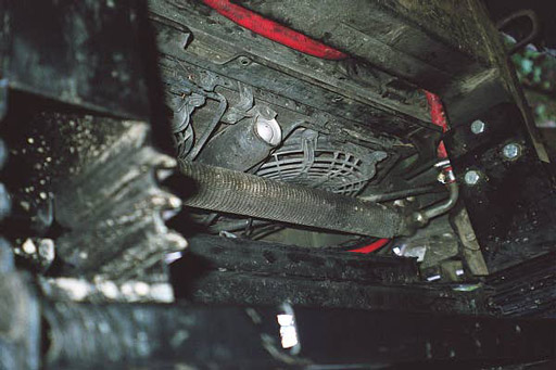
Once the plastic is removed you can clearly see the transmission cooler in Photo 2, and if you look at your vehicle, you will see the transmission line that will get in the way of the RE winch. Unbolt the passenger side transmission line where it enters the cooler (have a wide dish available to collect the fluid). Once unbolted, the transmission line will hang down on its flexible hose that extends back and connects to another solid line that is bolted to the lower part of the engine, just above the sump. I made my first cut here, with a hacksaw, just a little way back from the point where the stock flex hose meets the solid pipe, on the driver's side of the engine. I next cut the line about 1ľ inch from the first 90 degree bend right where the line extends from the cooler. You can see this in the right central area of photo 1 close to where the 3 bolts secure the bumper to the frame. I replaced the stock line with flexible hose that spans from the engine to the just below the cooler. I bought 4˝ feet of the 3/8 inch flex hose and trimmed it to the required length, routing it in such a manner as to avoid the area the winch would occupy. Note: the red you see above the transmission cooler is not the t-line but the positive lead that is connected to the battery. Finally, I cut a very small part of the front plastic grill. I used a dremmel tool to trim the lowest rail. Only a small amount needs to be cut and really is not visible from the front.
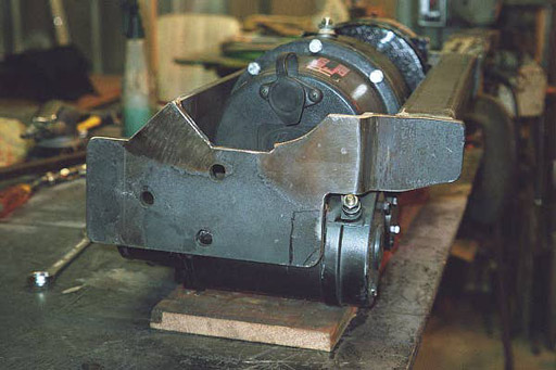
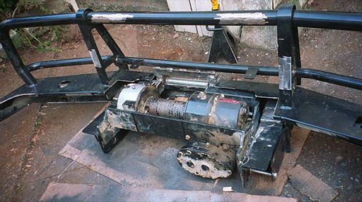
Previously I had a local fabricator make a brace for the RE winch. The original setup can be seen in the photo above. The same brace was used in the second round although a few changes were necessary. Essentially, I moved the entire brace up and forward several inches and welded it to the ARB bumper. I also modified the brace to take care of some initial design problems on the first attempt and to allow the cable to wind from the top of the drum and not the bottom. This involved opening and the reinforcing the front and rear of the brace in order to create a little more space to prevent the cable from jamming when it bunches up one side.
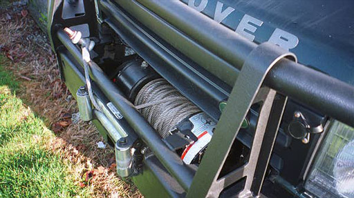
While raising the winch I also had to relocate the fairlead up to a higher point. In the photo above you can see that I slightly recessed the fairlead into the bumper and ended up placing it flush against the round tube that runs across the front of the ARB. In the same photo, you will notice that the winch solenoid pack has been removed and was relocated under the hood. This is documented here in an earlier article. A different perspective is provided in the photos below, which show the RE getting a test fit.
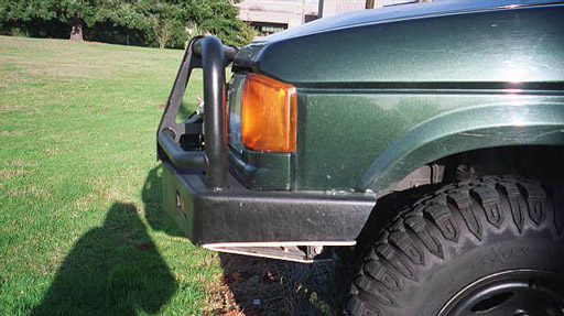
To create a better approach angle, I trimmed down the leading edges of the bumper removing the entire lower portion of the wings and cutting 2-3 inches from the center portion. I ended up trimming even more than is seen in the photos above. The second step to improve the approach angle was to pull the entire bumper in towards the vehicle by approximately 2 inches. This involved shortening the crush cans, removing the antenna tabs from the bumper, and grinding and cutting the wings to fit snuggly against the plastic trim under the front lights.
After the bumper was trimmed to fit and I was happy with the position of the RE, the next stage involved strengthening the bumper. I welded the shortened the crush cans in place and reinforced them with angle iron, flat bar, and square tube. The wings were similarly reinforced with square tube and angle that runs the perimeter and then cuts back across to the center of the bar. While you cannot see the steel framing in the photos below, the entire wing is gusseted to prevent movement. I covered the steel frame with aluminum plating.
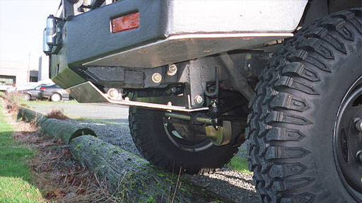
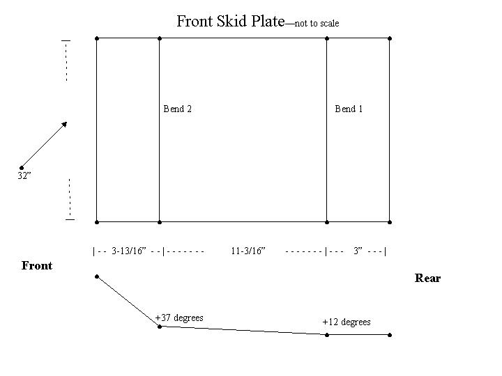
The next step was to make the lower plate. I had two goals in mind when making the ‘skid plate’. The first was to protect the RE from potential damage and exposure and the second was to add support to the ARB and help prevent twisting of the bumper. I welded two tabs, one on each frame rail, just forward of the tie down points. I then made a small brace that would support the aluminum plate and bolted everything in place. I designed the lower plate to act less as a form of protection for the steering linkage, as I had already replaced the stock links with heavier steering links from Rovertym Engineering. Part of my reasoning for not dropping the plate lower was to prevent it getting caught on a rock or root when one has to reverse off an obstacle for another attempt, but I am still wondering if I should have brought it down a bit further. The slide below provides the details for the aluminum plate. I had this cut and bent at a local sheet metal shop along with the small pieces that covered the wings.
In the past months I have tested the new setup on the trail. Even though I have a few minor changes in mind when I remove the bumper to repaint at some later point, I am satisfied with the end result. The bumper has taken some solid hits without shifting, and now I feel more confident that the ARB can protect my front end. The approach angle is much improved, especially in front of the tires, and given that it usually the rear end taking the heavier hits, I feel the approach angle is about right for my purposes.
Here are some links to photos when the Discovery still had the Bearmach HD springs. Front View and Side View. The extra weight in the front proved too much and I ended up trading over to OME springs from Expedition Exchange, placing a set of 764s in the front and 762s with a 1-inch spacer in the rear.