by Mike Rupp
Parts list: (assuming that you already have the winch installed)
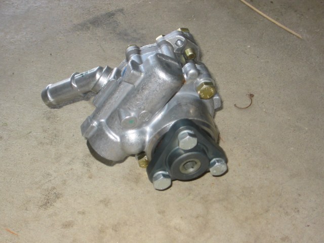
ZF74 pump, pulley, and relief valve set to 60 bar.(1100 psi) All available from 4x4winches.com
Hoses: high pressure line from pump to winch (you can use the old line from the winch install), high pressure line from winch to relief valve, and short hose from relief valve to steering box. You will need to measure the distances for each hose taking into account where the relief valve will be installed.
Hydraulic fittings:
high pressure side: T-fitting that fits into the relief valve and connects the high pressure hoses
low pressure side: T-fitting that fits into the relief valve and two 3/8" I.D. barbed adapters and hose clamps to connect the relief valve into the low pressure line from the steering box to reservoir
ATF
Introduction:
I ran the 9K Milemarker hydraulic winch for a year or so with decent results. However, there were quite a few times that the winch stalled using the standard LR pump. There are a few ways to get the hydraulic pressure needed to power the Milemarker, but I decided on replacing the stock pump with a higher rated ZF pump. The reasons that I chose this method rather than others was simplicity of installation, simplicity of operation and cost. Once installed, this system operates exactly like normal, except it has much more power.
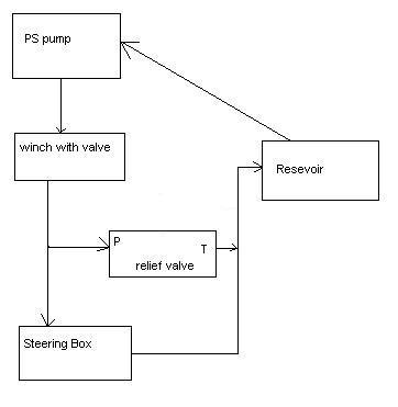
This method involves replacing the stock pump with a higher rated pump and installing a relief valve to lower the hydraulic pressure that goes to the steering box. The new pump is rated at 1850 psi, which is more than the steering box can handle. The standard installation has a high pressure hose that goes from the ps pump to the winch. This hose will be used as before. The standard installation has a high pressure hose that goes from the winch to the steering box. In this installation this hose will be replaced by 2 high pressure hoses with the relief valve in the middle. The other side of the relief valve is plumbed into the low pressure hose that goes from the steering box to the reservoir. Essentially what happens is when the pressure increases over 1100 psi, a spring in the relief valve compresses and opens up the valve. This allows fluid to bleed off the high pressure side into the low pressure side. The bleed off from the relief valve must be plumbed into the steering box to reservoir hose. This allows bubbles that are formed when the valve opens to be dissipated in the reservoir.
Here is a simple diagram that shows how the system is plumbed:
Installation:
Remove fan shroud
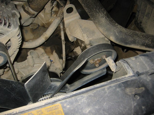
Remove the 3 bolts on the front of the pulley. Keeping the serpentine belt on makes them easier to remove.
Remove the serpentine belt.
Remove pulley.
Remove the bolts that attach the bracket to the housing.
Removing all of these things first will give you more room to access the
high pressure line on the bottom of the pump, which is a pain to remove.
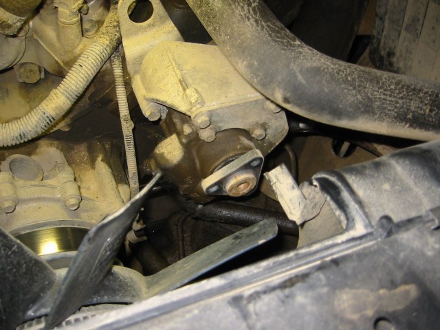
Remove the hoses from the bottom of the pump. Use a flare nut wrench to remove the high pressure fitting. You will need a low of torque to remove the fitting & an standard open-end wrench can slip and round out the fitting. Have a something underneath ready to catch the ATF that will come out.
Remove the bolts that attach the pump to the housing on the inside. You will need a 6" extension to reach the inside bolts. Having an air ratchet will speed things up.
Remove the pump from the housing.
Install the new pump. If I remember correctly, you'll
need to transfer a small bracket from the old pump to the new one.
Install the hydraulic lines to the pump and reinstall all of the pieces that were earlier removed. Make sure to install the new pulley that came with the winch.
Remove the high pressure line from winch to steering box and
reinstall with the new hose (slightly shorter to allow for relief valve)
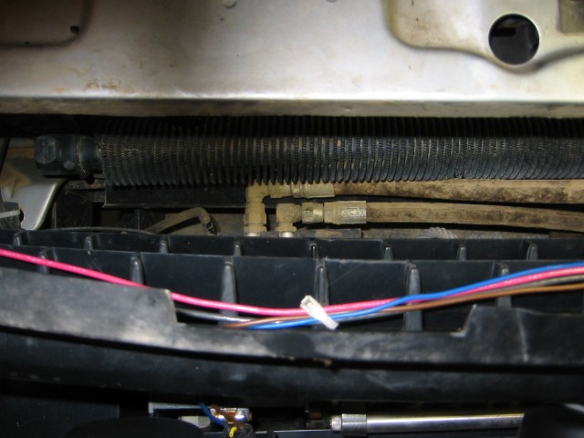
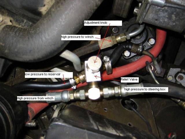
Assemble the relief valve. The "P" port is the high
pressure side. Screw in the T-fitting. The "T" port
is the low pressure side. Screw in the T-Fitting and the barbed connectors
for the low pressure hose. Look at the picture to get an an idea of
how everything is oriented.
Cut into the low pressure line from steering box to reservoir and attach the low pressure side of the relief valve.
Attach the high pressure hose from winch line to the relief valve. Attach the small high pressure hose to the relief valve and the fitting on the steering box. At this point, everything is completely installed.
Fill up the reservoir with ATF and start the engine for a few seconds. You will need to refill the reservoir. Once the system is full, check for leaks. I needed to remove the relief valve and tighten the T-fittings. It's a little difficult to know, at first, how hard to tighten the T-fittings since the relief valve is aluminum. I was concerned about stripping the valve body.
Once you're completely free of leaks, bleed the steering box. There is a small bleeder screw on the top of the steering box. With the engine running, open the screw and wait until fluid flows out. Turn the steering wheel lock to lock and bleed again.
Notes:
I initially installed the bleed off from the relief valve into the larger low pressure line (supply line to pump). This didn't work well at all. When turning at low speeds, air bubbles caused by the relief valve would cause the pump to cavitate. Not good! I reinstalled into the other low pressure line; problem solved!
My relief valve was not set at the proper pressure. Since it was set too low, the relief valve would open even when turning. Again, this is not a good thing! To reset the relief valve, unscrew the small lock ring on the relief valve and tighten the large brass knob. Tightening increases the relief pressure. Be careful; only move the knob 1/6 of a turn at a time. When I get a chance, I will get a pressure gauge to properly set the pressure. Here's a website that sells a gauge with the proper fittings: http://www.winchesplus.com/index.html Make sure to attach the gauge after the valve (steering box side). Set the pressure to 1100 psi. Determine pressure by turning steering to full lock and observe pressure.
Use this information at your own risk.