By Dave Brown
3/5/02
Introduction:
The M-1 antenna mounting bracket was designed to facilitate mounting long / full length ham radio and CB antennas on a Series 1 Land Rover Discovery.Ā Due the mass of long 102" stainless steel whip antennas, wind loads incurred while highway driving and shock loading while driving off road, the mounting plate for such antennas must be strong, yet be simple to install and maintain a minimum impact on the overall aesthetics of the vehicle.Ā The primary motivation for the development of the M-1 bracket has been driven by the need to have good high voltage RF insulation at the antenna base to accommodate high power ham radio installations.
Standard 3/8"-24 thread antenna mounting hardware is used for the ease of mounting off the shelf antenna products for both Ham Radio and CB applications.
For standard CB radio applications, M-1 mount could be made with a 1/2" antenna mounting hole which would accommodate standard 3/8" insulating shoulder washers.Ā The heavy and large diameter insulating washers used in this installation were done so to accommodate the high voltages incurred with an Icom 706MKIIG ham radio transceiver using an AH-4 automatic antenna tuner.
The antenna bracket can be fabricated from the detailed drawing at the end of this document.Ā
I had the M-1 antenna bracket custom manufactured by the Kennebunk Road Design Team, of Alfred, Maine. The Kennebunk Road Design Team is also the manufacturer of the Out-Back Expedition Antenna Mount for the Land Rover Discovery.Ā To obtain an M-1 bracket or a custom variation, you can contact the Kennebunk Road Design Team at [email protected]
Required Materials:
* See instructions for insulating washer fabrication from 3/8" nylon material stock
Required Tools:
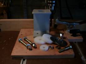
Figure 1:Ā M-1 bracket and all required
Hardware for assembly
M-1 Bracket Installation Procedure:
1. Begin by removing the passenger side bumper end cap.
a. Using a 13mm wrench, loosen and remove the two bumper end cap mounting bolts.
b. Remove the end cap by sliding it to the side and away from the vehicle.
c. Unsnap the running lamp bulb and tuck the wire assembly out of the way.
d. Set the end cap aside for the time being.
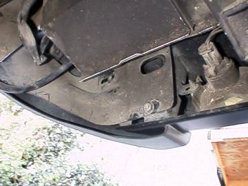
Figure 1:Ā Bumper end cap mounting screws (the top screw is already removed)
2. Clean the surface of the M-1 mounting area on the body tab that extends from the rear of the vehicle.
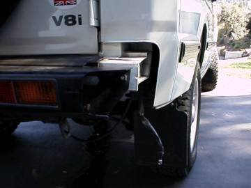
Figure 2:Ā End cap removed and the mounting area is cleaned up
3. Trim the bumper end cap to accommodate the M-1.
a. A small 1/2" deep cut out should be made on the back edge of the bumper end cap the allow clearance space for the M-1
b. Using a craft knife, cut a 1/2" deep 3-1/2" long notch.Ā Refer the Figure 3.
 |
4. Mark the antenna bracket mounting position on the vehicle.Ā Take time to make sure everything is centered right, Measure twice, drill once!Ā Refer to the diagram in Figure 4 for the correct drill position.
 |
Figure
4:Ā M-1 mounting position drawing
5. Using double sided tape (carpet tape works best) temporarily attach the M-1 bracket to the marked out position.Ā Take the bumper end cap and slide it back onto the bumper the make sure the mount is in the right place.Ā It might also be advisable to open the rear door to check for clearance. Ā
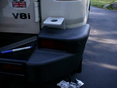
Figure 5:Ā Test fit of M-1 bracket with trimmed bumper end cap
6. Once the M-1 bracket position has been checked, close the rear door and remove the bumper end cap.Ā Carefully mark the M-1 mounting hole positions with a pen.Ā Remove the M-1 and double check the hole positions with a measuring scale and punch with a metal scribe or small nail.Ā These small indentations will stop the drill bit from wandering while drilling the first pilot hole.
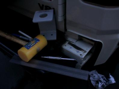
Figure 6:Ā M-1 mounting holes marked and ready to drill pilot holes
7. Drill M-1 mounting holes:
a. Begin by drilling two 1/8" pilot holes with a 1/8" drill bit and hand drill.Ā Make sure to drill through both the top and bottom sections of the tab extending from the vehicle body.Ā Make sure the top and bottom holes are perpendicular to the top of the body tab which has a downward slope of approximately 5░ to 7░.Ā The bottom plate of the M-1 bracket is offset by 5░ to compensate for the slope of the mounting area.Ā If the holes are not perpendicular to the slope of the body, the mount screws for the M-1 will not thread through straight.
b. Once the pilot holes are drilled, change drill bit to a larger size.Ā It is best to step up in drill sizes to several increments to the final size of 5/16".Ā This will help in drill clean holes and maintain the holes position.
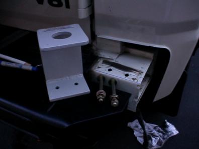
Figure 7:Ā M-1 mounting holes drilled
8. M-1 Mount to the vehicle using two 5/16"-24 x3" bolts, fit the M-1 to the vehicle body.
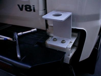
Figure 8:Ā M-1 Fitted to the vehicle
9. Secure the M-1 bracket to the body using several 5/16" fender washers, lock washers and 5/16"-24 nuts.Ā Apply loctite #242 to the fastener threads to assure the assembly will never vibrate loose when subjected to the rigors of off-road use.

Figure 9: M-1 secured to the vehicle
10. With the M-1 bracket secured, complete the antenna mount assembly.Ā Refer to Figure 10.
 |
Step 10 continued:
a. Take the 3/8"-24 x 2" antenna mounting bolt, slide on the following items in ascending order:
i. Ā3/8" lock washer
ii. 3/8" flat washer
iii. Antenna feed line ring terminal
iv. 2" outer diameter stainless steel fender washer
v. 2" nylon insulator
vi. 1-1/4" nylon insulator
b. Thread the assembly up through the M-1 bracket and drop on the final assembly items in ascending order:
i. 2" nylon washer
ii. 2" outer diameter stainless steel fender washer
iii. 3/8" flat washer
iv. 3/8" - 24 antenna coupling mounting nut
c. Tighten the assembly using 7/16" and 5/8" open end wrenches
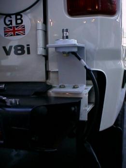
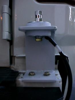
Figure 11: Completed M-1 antenna mount assembly
11. Re-assemble the bumper end cap over the base of the M-1 antenna mount assembly.Ā Secure with the fasteners, which were removed in the first step of this procedure.Ā Tighten with a 13mm wrench.
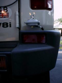
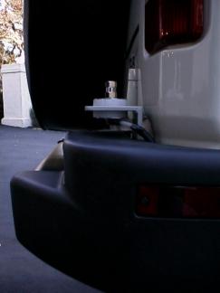
Figure 12:Ā The completed assembly
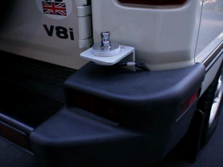
Figure 13:Ā Another view of the completed assembly
12. Install the antenna to be used with the M-1 mount, test, use and enjoy!
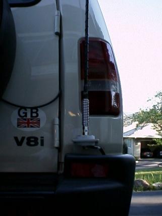
Figure 14:Ā Final M-1 assembly with antenna
 |
Detailed drawing of the M-1 Bracket:
Insulating Washer Fabrication
Introduction:
The nylon insulating washers used with the M-1 prototype antenna mount were not readily available and were custom manufactured.Ā The washers were cut from 3/8" thick nylon stock.Ā The nylon material is commonly available at wood working supply stores for making custom jigs.Ā A good source is Rockler, Inc. (www.rockler.com).Ā Any sturdy phenolic or ceramic material with good electrical insulating properties could be substituted, but these materials are more difficult to obtain and work with.
A band saw was used to cut the circular insulator blanks out.Ā A scroll saw, jig saw or with a little thought a large size hole saw could also be used.
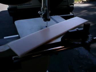
Figure 1:Ā 3/8" Nylon material blank
Insulator Washer Fabrication Procedure:
Two 2" x 3/8" thick washers and one 1-1/4" x 1/4" washer all with 3/8" center holes are required.Ā Refer to the following drawings for washer dimensions and layout:
 |
Figure 2:Ā Nylon washer dimensions
1. Start out by cutting the blank material into a few strips and mark out the circles to be cut.Ā
2. The material piece to be used for the 1-1/4" washer is planed to a 1/4" thickness.Ā
3. A 5/32" center hole was drilled for each washer for attachment to a circle cutting jig.
4. Make a simple circle cutting jig for a band saw by using a 8"x8" piece of 3/4" MDF stock.Ā Plywood or any similar flat piece of scrap wood will work.Ā On the center of one side of the piece of wood, drill a 9/64" pilot hole 3/4" in from one edge.Ā This will be used as the circle cutting jig center guide with the use of a 1" #6 flat head wood screw.Ā The cone shape at the head of the screw will help self center the work piece.
5. Attach a material piece to be cut to the cutting jig.Ā Set the jig distance for the appropriate circle radius and secure the jig the saw table top with a few clamps.
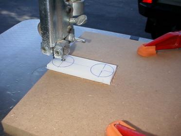
Figure 3:Ā Washer blank set up on the circle cutting jigĀĀĀĀĀ
6. Cut out a washer and repeat the process to make the quantity needed.Ā Finish all edges with fine grade sand paper (220 grit works fine).
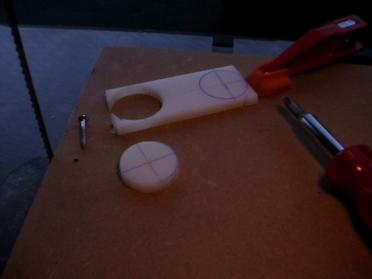
Figure 4:Ā Cut out washer
7. Set up a drill press or substitute with a hand drill if a drill press is not available.Ā Secure the cut out washer blanks and drill a 3/8" center hole.
8. Gather all the piece parts for the antenna mount and fit the assembly before mounting on the vehicle.
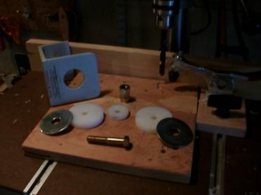
Figure 5:Washers and antenna hardware

Figure 6:M-1 and necessary parts
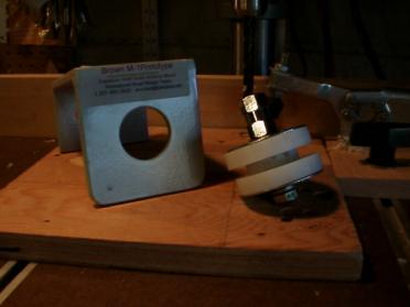
Figure 7: M-1 and antenna mount assembly
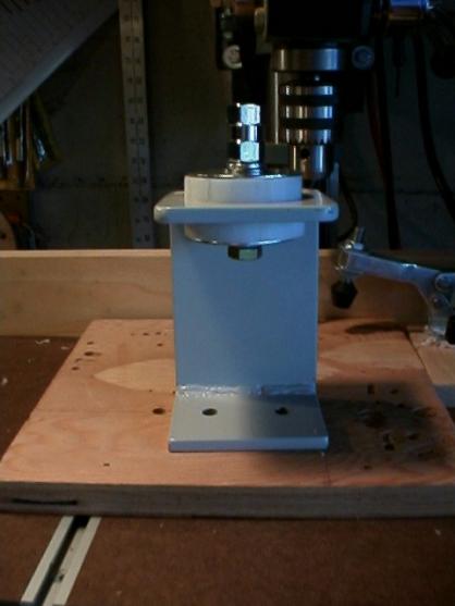
Figure 8: Complete M-1 antenna bracket