In case anyone is interested, I recently went through a nightmare with my 96 D1 ABS system. The brakes worked fine, but the ABS light came on 4 months ago and I couldn't get the problem fixed and the light extinguished.
The original blink code was for the left rear sensor air gap. I fiddled with that sensor but it looked fine and the resistance and voltage tests indicated it was OK, so pulled both rear sensors, swapped them left to right and then got a whole bunch of other codes which made me think the ECU had gone schizoid")
I put the rear sensors back in their correct spots and then got a front left sensor bad connection code. I pulled the sensor and did the resistance and voltage checks and it seemed fine, so I reinstalled it. Still got the bad connection code so I pulled it again and this time I noticed intermittent readings on the resistance test... When bending the cable back and forth close to the top of the sensor, I noticed the resistance would go from normal (~ 0.998 ?) and then change to infinite (e.g.: open circuit = broken wire).
I reinstalled the sensor in such a way that the wires in the cable were "connecting" and I was getting a normal resistance reading when it was all tied down, but I still got the bad connection code when I plugged the sensor into the ECU, so I decided that since the cable was f@%#ed, I would tear it apart and see if I could fix it.
The sensor is basically a tall stainless cup with a solid plastic cap that goes in quite a distance into the cup. You cannot pull the plastic plug out (at least I couldn't for fear of damaging the stainless housing), so I used my Dremel tool with a tiny grinding bit and ground out the plastic plug to a depth of about 1/2" into the cup.
I peeled away the black silicone insulation sheath from about 2" of exposed cable back from the sensor which revealed 2 wires (~ 16 Ga), one black and one brown. I then peeled the insulation from these two wires and found that the brown wire was broken clean through. The location of the break was right at the point where the cable meets the top of the plastic top on the sensor, which indicates that the reason for the break was fatigue (repeated bending of the cable at the top of the sensor which eventually led to the break). I'll talk about yet another example of piss poor LR design later since having taken the sensor apart, I can say it is a pretty well made "instrument" except for the fact that there is no stress reliever built into the head of the sensor, thus creating an inherent concentrated stress point which will lead to certain failure over time. Every time the wheels are steered left or right, the ABS cable is flexing and the wires are hardening...
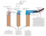
I did a resistance check of the sensor itself using the newly exposed wires protruding from the top of the sensor and the readings looked good, so I decided to attempt a repair. I wanted to improve the bad design so I made up a pair of "dog leg" shaped wires to act as pins from the top of the sensor. I made these by stripping 2 short pieces of 12 Ga wire of their insulation and coating them with solder so they were stiff after they were bent up (see sketch). I then soldered the 2 wires to the short wires in the top of the ABS sensor. I then used a really good 2 part potting compound called "Marine-Tex" to seal and secure the stiff "dog leg" wires into place. Once the potting compound had cured, I soldered the original ABS cable wires back to the pins on the sensor and made up a stiffener using a small piece of polycarbonate (Lexan) sheet which I heat formed over the coated pins just for extra strength.
I then applied another coat of potting compound to cover the polycarb and seal the wires. Once it was all cured, I re-installed the sensor and the code was gone. No more ABS light
Now my rant on LR design... As I mentioned earlier, the ABS sensor has an inherent design flaw in that there is no stress reliever incorporated around the cable where it joins to the top of the sensor. This is definitely a no-no and Wabco should know better. However, the design folks at LR should have recognized this as a problem and done a better job (due diligence) in designing how the sensor is mounted to the wheel hub ! All it would take is a fastening point for the cable somewhere near the ABS sensor location so that the cable could still flex but not at the top of the sensor. It's not rocket science, anybody with the slightest amount of common sense would know this !! The result is that an instrument with no moving parts which should last forever now fails at about 70K miles (at least for me). I'm guessing the replacement cost for one of these sensors is about $150, and if you consider the cost that would normally be incurred by getting this diagnosed and fixed at the stealership, you would probably be looking at over $300 per wheel. This is bullshit given that the sensor itself still works.
So, with all the money I'm saving by repairing all these crappy LR design issues myself, I will be able to get a return ticket to the UK so I can go to LR and personally bitch slap the designers for being such f@%#tards !
KevLar
The original blink code was for the left rear sensor air gap. I fiddled with that sensor but it looked fine and the resistance and voltage tests indicated it was OK, so pulled both rear sensors, swapped them left to right and then got a whole bunch of other codes which made me think the ECU had gone schizoid
I put the rear sensors back in their correct spots and then got a front left sensor bad connection code. I pulled the sensor and did the resistance and voltage checks and it seemed fine, so I reinstalled it. Still got the bad connection code so I pulled it again and this time I noticed intermittent readings on the resistance test... When bending the cable back and forth close to the top of the sensor, I noticed the resistance would go from normal (~ 0.998 ?) and then change to infinite (e.g.: open circuit = broken wire).
I reinstalled the sensor in such a way that the wires in the cable were "connecting" and I was getting a normal resistance reading when it was all tied down, but I still got the bad connection code when I plugged the sensor into the ECU, so I decided that since the cable was f@%#ed, I would tear it apart and see if I could fix it.
The sensor is basically a tall stainless cup with a solid plastic cap that goes in quite a distance into the cup. You cannot pull the plastic plug out (at least I couldn't for fear of damaging the stainless housing), so I used my Dremel tool with a tiny grinding bit and ground out the plastic plug to a depth of about 1/2" into the cup.
I peeled away the black silicone insulation sheath from about 2" of exposed cable back from the sensor which revealed 2 wires (~ 16 Ga), one black and one brown. I then peeled the insulation from these two wires and found that the brown wire was broken clean through. The location of the break was right at the point where the cable meets the top of the plastic top on the sensor, which indicates that the reason for the break was fatigue (repeated bending of the cable at the top of the sensor which eventually led to the break). I'll talk about yet another example of piss poor LR design later since having taken the sensor apart, I can say it is a pretty well made "instrument" except for the fact that there is no stress reliever built into the head of the sensor, thus creating an inherent concentrated stress point which will lead to certain failure over time. Every time the wheels are steered left or right, the ABS cable is flexing and the wires are hardening...
I did a resistance check of the sensor itself using the newly exposed wires protruding from the top of the sensor and the readings looked good, so I decided to attempt a repair. I wanted to improve the bad design so I made up a pair of "dog leg" shaped wires to act as pins from the top of the sensor. I made these by stripping 2 short pieces of 12 Ga wire of their insulation and coating them with solder so they were stiff after they were bent up (see sketch). I then soldered the 2 wires to the short wires in the top of the ABS sensor. I then used a really good 2 part potting compound called "Marine-Tex" to seal and secure the stiff "dog leg" wires into place. Once the potting compound had cured, I soldered the original ABS cable wires back to the pins on the sensor and made up a stiffener using a small piece of polycarbonate (Lexan) sheet which I heat formed over the coated pins just for extra strength.
I then applied another coat of potting compound to cover the polycarb and seal the wires. Once it was all cured, I re-installed the sensor and the code was gone. No more ABS light
Now my rant on LR design... As I mentioned earlier, the ABS sensor has an inherent design flaw in that there is no stress reliever incorporated around the cable where it joins to the top of the sensor. This is definitely a no-no and Wabco should know better. However, the design folks at LR should have recognized this as a problem and done a better job (due diligence) in designing how the sensor is mounted to the wheel hub ! All it would take is a fastening point for the cable somewhere near the ABS sensor location so that the cable could still flex but not at the top of the sensor. It's not rocket science, anybody with the slightest amount of common sense would know this !! The result is that an instrument with no moving parts which should last forever now fails at about 70K miles (at least for me). I'm guessing the replacement cost for one of these sensors is about $150, and if you consider the cost that would normally be incurred by getting this diagnosed and fixed at the stealership, you would probably be looking at over $300 per wheel. This is bullshit given that the sensor itself still works.
So, with all the money I'm saving by repairing all these crappy LR design issues myself, I will be able to get a return ticket to the UK so I can go to LR and personally bitch slap the designers for being such f@%#tards !
KevLar