
Pinout diagram for Disco 1 Radio Amplifier
- Thread starter 61rover
- Start date
You are using an out of date browser. It may not display this or other websites correctly.
You should upgrade or use an alternative browser.
You should upgrade or use an alternative browser.
ptschram
Well-known member
ptschram
Well-known member
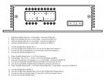
Pins 5/15 Rite rear output
pins 8/18 left rear out
pins 6/16 Rite front
pins 7/17Left front
inputs
pins 1,2,3,4 inputs hot
Pin 11 ground.
The ETM is not very forthcoming with further identifying the inputs.
pins 8/18 left rear out
pins 6/16 Rite front
pins 7/17Left front
inputs
pins 1,2,3,4 inputs hot
Pin 11 ground.
The ETM is not very forthcoming with further identifying the inputs.
The 1996 Land Rover Discovery factory cassette stereo is a Pioneer KEX-910ZRV. The amp is also a Pioneer but I don't have the part number handy...
I purchased an e-manual a while back for the radio because I wanted to use the CD changer input to feed my iPod through, but it turned out that this would have been very difficult to do, so I ended up replacing the stock deck with a Blaupunkt Seattle, and now my iPod is fully integrated.
If it's helpful, I can post the Pioneer KEX-910ZRV manual for you. Additionally you can try the following links that were I came across during my research:
http://www.ued.net/website/index.html <-- Online manuals including Pioneer
http://carstereohelp.net/wireharness_LandRover2.htm <-- A page about the Pioneer KEX-910ZRV radio wiring harness
A
adi
Guest
I don't think I have the pics anymore, but when I bypassed the stock amp, I tied into the 4 pairs pointing toward the rear of the truck. Mine is also a '96, if you want I can try and get some more pics of it.
It is the Pioneer amplifier from a 96 Disco 1. It has one large rectangular plug. I'm trying to retrofit the stock Pioneer head unit and amplifier into my Defender. I have all the info on the head unit but can't find the same for the amplifier. The previous owner removed all the stock stereo wiring and I'm having to wire it all from scratch.
ptschram
Well-known member
61rover said:It is the Pioneer amplifier from a 96 Disco 1. It has one large rectangular plug. I'm trying to retrofit the stock Pioneer head unit and amplifier into my Defender. I have all the info on the head unit but can't find the same for the amplifier. The previous owner removed all the stock stereo wiring and I'm having to wire it all from scratch.
I might have a wiring harness. Lemme take a looksee.
Re: Pinout diagram for Disco 1 Radio Amplifier - See attached
I put together some drawings for you relating to the '96 Disco power amplifier wiring. There are 6 .jpg images of the various connectors taken from the LR Workshop Manual and 1 drawing I made of the power amp and connector pin-outs for the 1996 NAS Disco. The "CXXX" in the file names refers to the connector number in the Workshop Manual. Note that there are 2 radios listed for the '96 Disco, the "Low/Medium Line" and the "High Line". The info I'm providing is from the Low/Medium Line Radio:
C2054 Power Amp Connector.jpg
C260 Radio Connector (Speakers).jpg
C230 Radio Connector (Remote).jpg
C268 Radio Connector (Power).jpg
C412 Sub Woofer Connector.jpg
1996 Land Rover Power Amp Pin-Outs.jpg
Last year I had to replace my power amp because the circuit board had failed due to galvanic corrosion Pretty poor design in my opinion... When I called the dealer, I found the price of the amp was something like $450, so I first thought of replacing the stock amp with a good 3rd party amp for less than replacing the OEM amp. I pulled the stock amp and radio and traced all the pin-outs, but then I ended up finding a used amp on eBay from RoverGuy.com for about $50. When I installed the used amp I also pulled the stock LR radio/cassette deck and replaced it with a Blaupunkt, and wired my iPod into it
Anyway, hope this helps, and let me know if you have any questions
Cheers !
Kev
I put together some drawings for you relating to the '96 Disco power amplifier wiring. There are 6 .jpg images of the various connectors taken from the LR Workshop Manual and 1 drawing I made of the power amp and connector pin-outs for the 1996 NAS Disco. The "CXXX" in the file names refers to the connector number in the Workshop Manual. Note that there are 2 radios listed for the '96 Disco, the "Low/Medium Line" and the "High Line". The info I'm providing is from the Low/Medium Line Radio:
C2054 Power Amp Connector.jpg
C260 Radio Connector (Speakers).jpg
C230 Radio Connector (Remote).jpg
C268 Radio Connector (Power).jpg
C412 Sub Woofer Connector.jpg
1996 Land Rover Power Amp Pin-Outs.jpg
Last year I had to replace my power amp because the circuit board had failed due to galvanic corrosion
Pretty poor design in my opinion... When I called the dealer, I found the price of the amp was something like $450, so I first thought of replacing the stock amp with a good 3rd party amp for less than replacing the OEM amp. I pulled the stock amp and radio and traced all the pin-outs, but then I ended up finding a used amp on eBay from RoverGuy.com for about $50. When I installed the used amp I also pulled the stock LR radio/cassette deck and replaced it with a Blaupunkt, and wired my iPod into it Anyway, hope this helps, and let me know if you have any questions
Cheers !
Kev
Attachments
Last edited:
61rover said:Thank you VERY MUCH. I've had nothing but tire noise to listen to for several weeks.
John
:rofl: Yes, I imagine that sound must get pretty "tired" after a while, but still preferable to any Lionel Ritchie tune :banghead:
One thing I should highlight in case it's not immediately obvious: The 5 "CXXX" drawings I posted represent the "connectors" that terminate the various wire harnesses. They are not drawings of the connectors (plug-in points) on the pieces of hardware (e.g.: amp, sub woofer amp, radio). For example, if you look at "C2054 Power Amp Connector.jpg" out of the Workshop Manual, and compare that to the drawing of the pin-outs I made for the power amp box "1996 Land Rover Power Amp Pin-Outs.jpg", you'll notice that they are slightly different. First, the plug-in point (connector) on the power amp is upside down because I made the drawing with the amp base facing down. But if you rotate that drawing 180 deg so that the amp is upside down, you'll see that Pin 1 of the power amp plug-in is top right, while Pin 1 on the wire harness connector (C2054) is top left.
If you mentally rotate the connector so that the pins face the power amp connector, you'll see that the pins match up
- You probably already realize this, but I just wanted to make sure that you didn't inadvertently spend hours wiring everything up backwards.Another note, I was just going through the sketches and notes I made when I did my circuit tracing last winter and noticed that I had some ?? marks beside the entries for pins # 9 and 14 of the power amp connector. Keep in mind that I did not completely rewire my system like you are doing, I only changed the radio and replaced the amp with a used one that was identical, which is a pretty simple job. Therefore, I did not have to worry about Pins 9 & 14 since they did not interface with the radio and were already wired... The description in the text of the .jpg image (1996 Land Rover Power Amp Pin-Outs.jpg) is right from my notes and I did my circuit tracing using a multimeter and then checking readings with the ingition "off", then "accessory", radio "on" and "off", etc, to see what wires were switched to what.
For Pin 9, if you visually follow this pin from the power amp plug-in to the circuit board on the amp (you'll have to open the power amp box), you'll see that it connects to the 7.5 A fuse, so with my multimeter and sleuthing I determined that this must be the main power to the power amp. It does get power when the key is on.
For pin 14, I found that there was only power going to it when the radio was tunred on (e.g.: the power antenna wire from the radio would do this for you). I determined that this would be some sort of relay to apply the power (Pin 9) to the power amp. This is confirmed in the additional image "Radio (NAS) Circuit Diagram p. 6.jpg" from the Workshop Manual that I'm inlcuding. Look at the bottom of the image and you'll see a vertical line (wire) on the left # 14, and one to its right # 9 coming out of the "Radio Amplifier" box (Z175). You'll see that # 9 feeds to the Power Amplifier relay, but #14 is a little nebulous since it is shown connecting to "E7-2" above a triangle with a letter A in it. This symbol is supposed to mean that the line continues on another page, but I could not find it.
I'm including a few more .jpg files pulled from the Workshop Manual so you can look for yourself. Also, you might want to download the Land Rover Manual. I found a link for it last week and it had been a real timesaver
The files for each model/line are fairly large (400 MB) but it's worth the wait to download. Check out the following link:http://green-oval.com/joomla/index.php?option=com_docman&task=cat_view&gid=13&I
Cheers !
Kev
Last edited:
Re: Pinout diagram for Disco 1 Radio Amplifier - See attached
Not to bring up a thread from the dead, but is there any chance you could re-post the pics of the 6 .jpg images? I'm trying to figure out why my Disco's subwoofer suddenly went dead and the other 4 speakers are now very weak.
Might just give up and wire up an aftermarket deck and/or amplifier.
Thanks in advance!
-Darren
KevLar said:I put together some drawings for you relating to the '96 Disco power amplifier wiring. There are 6 .jpg images of the various connectors taken from the LR Workshop Manual and 1 drawing I made of the power amp and connector pin-outs for the 1996 NAS Disco. The "CXXX" in the file names refers to the connector number in the Workshop Manual. Note that there are 2 radios listed for the '96 Disco, the "Low/Medium Line" and the "High Line". The info I'm providing is from the Low/Medium Line Radio:
C2054 Power Amp Connector.jpg
C260 Radio Connector (Speakers).jpg
C230 Radio Connector (Remote).jpg
C268 Radio Connector (Power).jpg
C412 Sub Woofer Connector.jpg
1996 Land Rover Power Amp Pin-Outs.jpg
Last year I had to replace my power amp because the circuit board had failed due to galvanic corrosion
Anyway, hope this helps, and let me know if you have any questions
Cheers !
Kev
Re: Pinout diagram for Disco 1 tailgate subwoofer Amplifier
Pinout diagram for Disco 1 tailgate subwoofer amplifier A-4025?
Thanks.
Pinout diagram for Disco 1 tailgate subwoofer amplifier A-4025?
Thanks.
Last edited:
Look for connector C412 in the Discovery Electrical Manual as seen here: http://www.landy.ee/manuals/electricity/Disco_Elec.Troubleshooting Manual - LRL0077ENG (1997).pdfA-4025